Silencing my Switch

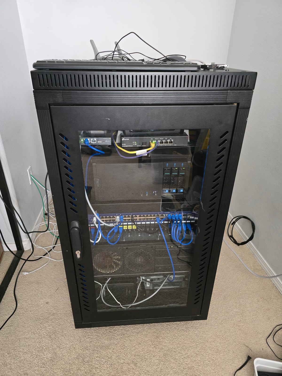
[pic of my switch]
I acquired a used 48-port Netgear GS748TP for free not too long ago. Everything on it seemed to work just fine and it even has POE! It has more ports than I'll ever need and is a great addition to my homelab.
It does have one issue though. The little fans on it run at top speed making them whine loudly at a high pitch. Normally in a server environment that would be okay, but in my home, it becomes a real annoyance. Here, I'll explore making this thing quieter.
[LinkedIn Plug]
Research
I'm sure people end up with used enterprise hardware all the time and end up with the same problem, so there must be some common mods. This switch shouldn't be too uncommon!
After a quick google search, I found a reddit post of someone replacing a similar Netgear switch's fans with much quieter Noctua fans!
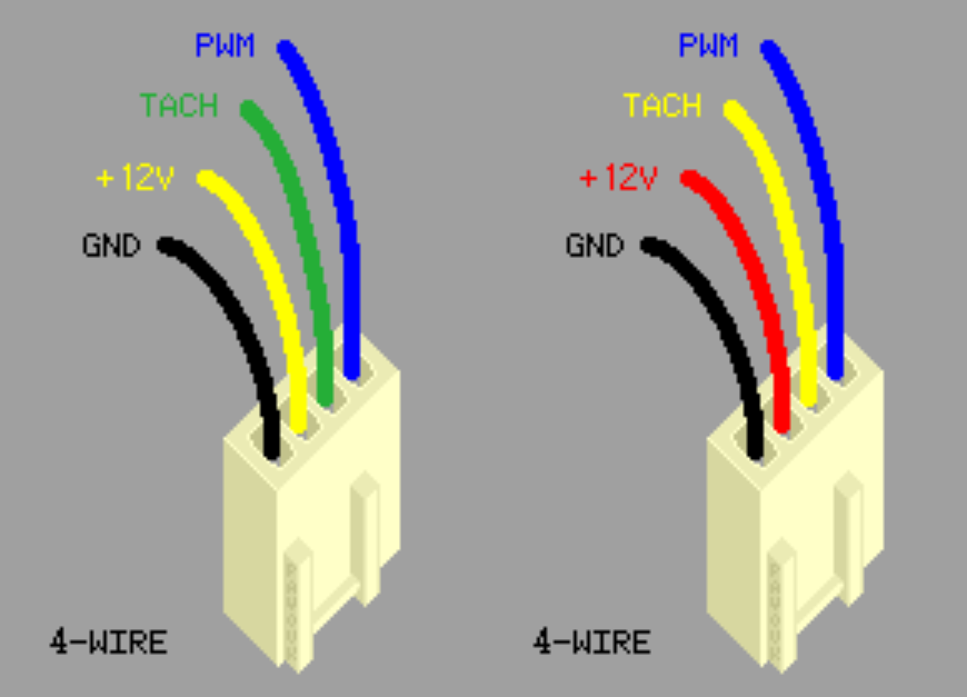
In that post, the user details that they're going to replace their Netgear's fans with 40mm Noctua 5V fans. They also show that you have to de-pin the new fan's connector to swap the order of the wires. It's odd that the switch isn't using a normal pin orientation, but oh well that's not too bad. Things are looking good!
Looking in the comments though, it seems a lot of people have ended up with their fans not working, despite following what OP did! The comments are riddled with confusion and obscurity. Heck, zooming in on the user's images, you can see the original fan is a 12V fan, but the new fans are 5V! Confusing indeed.
Instead of following the post exactly, I think I should poke around my switch and see what's going on.
Exploring my Particular Switch
After popping off the top of my switch's enclosure and grabbing my multi-meter, I can get a good look inside. I can easily confirm that the pin order was definitely not standard, so that was a good consistency to the post.
Removing one of the fans, I can get access to the fan header on the board. With the board powered off, I checked continuity between the pin matching with the black wire and the mounting screw on the board. My multi-meter got a good consistent beep, so at least that matches the assumption! I powered the switch on and measured the assumed-to-be power pin matching with the red wire's position. The reading was something like 11.9V, close enough to assume its 12V! At this point everything seemed like it was going to work out just fine, so I used some dupont wires to hook a 120mm fan's pins to 12v and ground on the switch's header as a test (I didn't have the 40mm fans on hand yet since I needed to confirm what voltage I truly needed before spending $75+ on little fans). After powering the switch back on, the fan did not turn on. 😦
Why Didn't that Work?
What? Giving a 12V fan 12V didn't make it spin? Was there some sort of resistance detection or current limiting going on so you only use the right fans?? I guess I understand why everyone is confused in the reddit post.
I unplugged everything and kept the switch on and measured the different pins again. By habit, when measuring voltage, I always pick a large, obvious ground on the board so I don't short something accidentally with my shaky hands when trying to carefully handle the precise location of two DMM probes at once. In this case, that ground point was one of the board's mounting screws. When I measure the potential between the ground screw and 12V, I get the same reading as before: 11.9V. That still seems good to me. This time, with the board still on, I checked the ground pin's continuity to the board's mounting screw. This time, instead of a continuous beep, I got several dozen discrete beeps per second. I immediately thought "PWM on the ground pin?"
[video of the ground pwm sound]
I quickly jumped to my next test where I tapped off the 12V from the pin on the fan header, and ground off the mounting screw. I just saw this as the most direct path to getting something to happen. This time, the fan I had patched-together absolutely ran at full speed! This means the pin on the fan header matching with the black wire on the delta fan was doing some trickery... I didn't want to deal with deciphering that sorcery since I had a possible direct path: Just tapping a normal 12V and ground directly from somewhere on the board.
My Plan
Well, despite not unlocking the full mystery of what's happening here yet, I could still achieve my goal of making my switch quieter by using what I learned. I'll just chop up some 40mm Noctua fans wiring to tap a direct, no-trickery 12V source by soldering or some other means. All that mattered now was that I could order some 12V Noctua fans and and not sweat it.
Looking at Noctua's product site for 12V, 40mm fans, I ran into this offering:
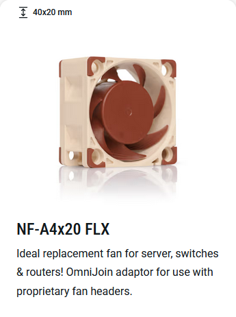

I knew this was a common enough problem!! I'm not going to have to solder anything; this kit comes with solderless splicers and a female fan header with pigtails! I can probably daisy chain the 12V pins to the original fan header on the board and connect all the grounds to that mounting screw. Incredible.
Overkill Drawings?
I like fully planning something out when I can so that I can make sure things make sense and that I have the right components necessary. It also makes it so I can upfront my thinking and I don't have to worry about figuring out details and assembling things correctly in the moment. I can just follow the plan and not think. So, to do this here, I'm going to make a quick wiring diagram.
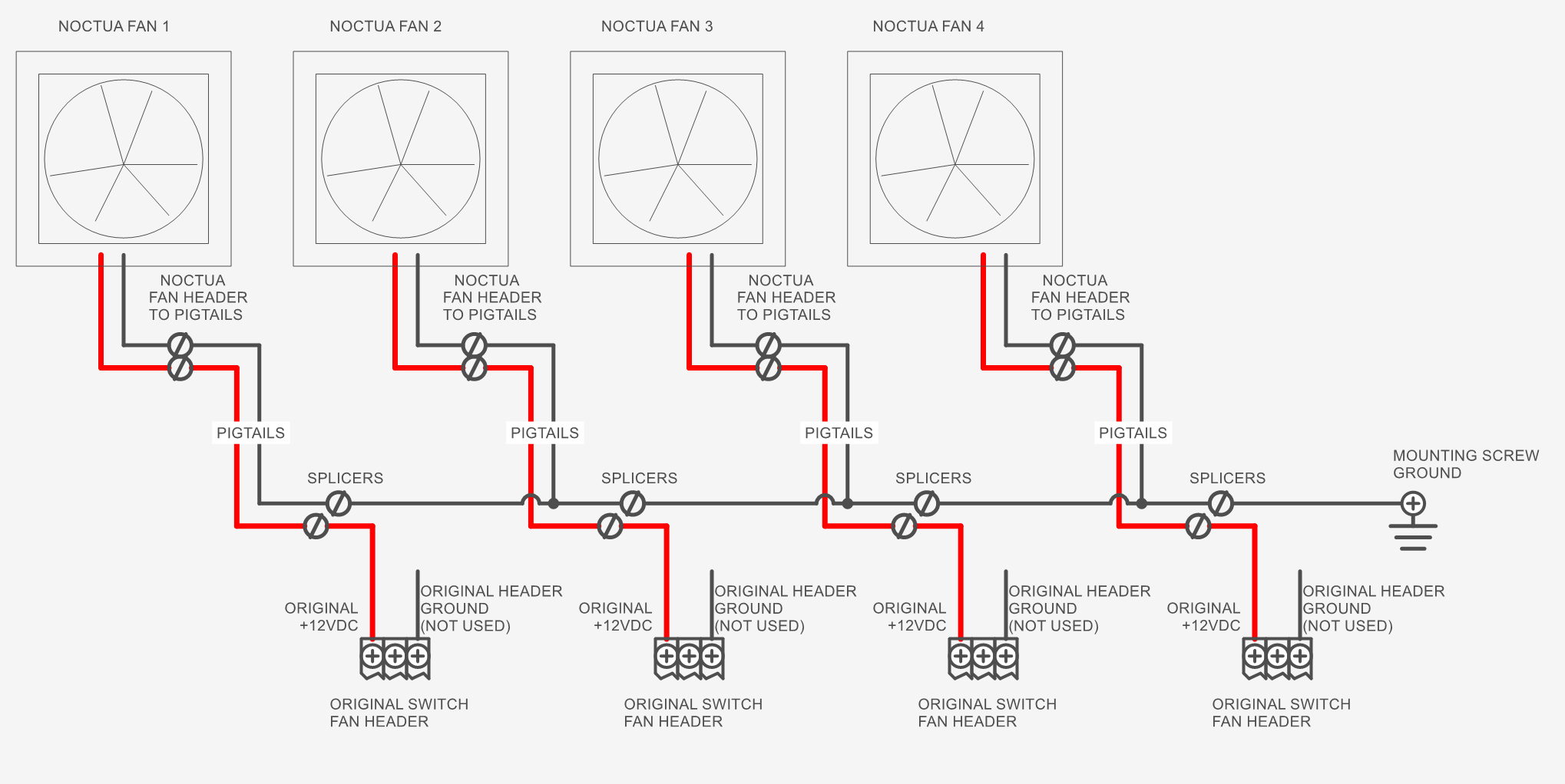
I decided to make one ground bus and then source 12V from each individual connector on the board. The plan will be to harvest the connector + wiring from the loud Delta fans, daisy-chain the grounds together to the Noctua pigtails, and splice together the original 12V pigtails to the Noctua pigtails.
[insert pics of irl harness here]
[insert pics of completed build here]
Was it worth it?
Overall, this setup is so much quieter and less annoying. Hopefully the video does this justice. I am now going to enjoy the peace and quiet of my hobby room (at least when the 3D printer isn't running.
Ugh, so loud and whiny!
[after video]
[LinkedIn Plug]
Solving the Mystery
Some commenters in that reddit thread seem to be getting 6V across the 12V and pseudo-ground pins. So maybe the switch is doing some PWM. It would explain why the 5V fan was working and not the 12V fan, but then why are the 12V-rated Delta fans working at full speed? And why do not all of the 5V fans work according to the commenters? Does the board require some special signal (tachometer?) from the mysterious blue wire to output the right PWM signal? If I had an oscilloscope I could find out a lot of this. But maybe it's not worth exploring since there's a simple work around.
Delta Fan Datasheet
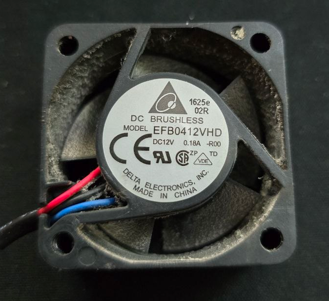
The part number for my delta fan is EFB0412VHD. Putting that into DigiKey yields a result:
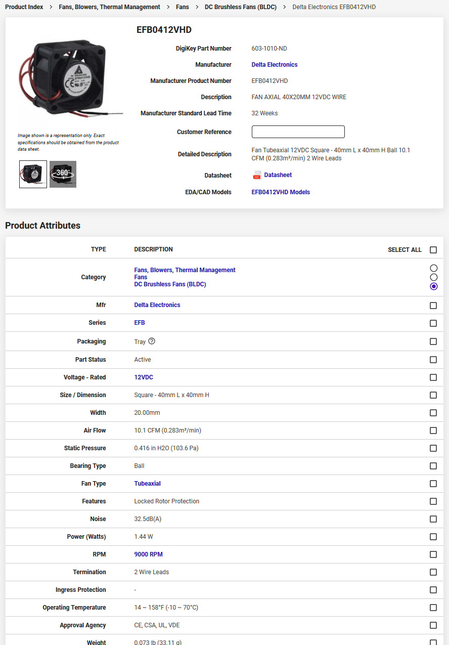
Well, everything looks okay mostly, except, this says it has 2 wire leads, but the one I have in hand definitely has 3 wires--And the part numbers match.
Early in the fan's datasheet, it says the minimum starting voltage for the fan is 5V. Meanwhile, the Noctua fan's starting voltage is 8V! If the fan header on the switch is truly PWM'd to 6V, then maybe that's why they don't work consistently. The datasheet didn't really show anything useful.
Looking at the DigiKey page, I am reminded these are all BLDC motors, which require an ESC (electronic speed controller) to work. These fans all probably have a little ESC embedded into them to make sure the coils are switched with he proper sequence and timing. So maaaaybe there's also some proprietary shenanigans going on with the delta fans--especially when the original part number only has 2 wires.
Aren't You Getting Way Less Airflow with the Noctua Fans?
Yes I am! The Noctua fans give out 5.53 CFM maximum while the Deltas give out 10.1 CFM, almost double. This switch has 48 ports on it and I'm never going to fill it up with that many devices. Currently I only have 3 POE devices, which are what's going to cause the most heat. If I make the terrible assumption that half the airflow means I can only plug in 24 POE devices, then that's fine with me (it'd actually be more like 12 devices, keep reading).
Ideally, one would measure the switch's temperature before and after the modification and see what difference that makes, but like I said, I am not fully populating this switch. I'll take the risk. If I were doing this for someone else professionally, I'd probably fully load the switch with POE devices and see what the temps are before and after.
To add to this, I think this is a regular POE switch (not POE+ or POE++) and its max POE budget is 384W. A POE device can take up to 15.4W, which means up to 24 POE devices can be plugged in at once normally. If I (again, naively) assume that I have half the cooling capacity, and thus half the POE budget, then I'd only be able to plug in 12 POE devices. Even if I wanted to upgrade to having a few POE cameras and devices, I currently don't have a need for 12 of them. This is a scaling problem that I'll have to deal with later.
I'm also not in a hot server environment; I'm in an air-conditioned home so the server has access to cool air 😻